
Telemetry Board
Overview
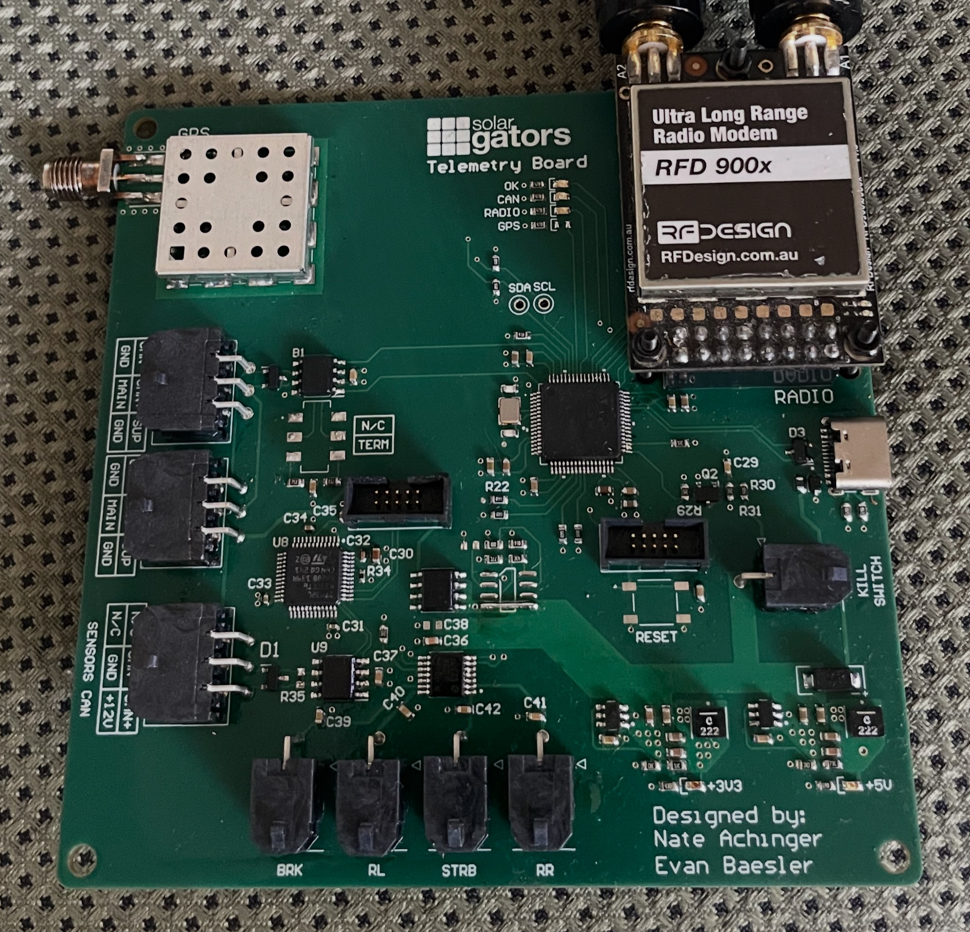
The data acquisition board for Flare, UF Solar Gators’ fourth solar race car that competed in the 2026 Formula Sun Grand Prix and American Solar Challenge. Responsible for wirelessly transmitting critical data received over the car’s CAN bus including main battery cell voltages and temperatures, MPPT power data, and motor controller data. Tracks the vehicles live position and speed through a built in GPS module. The board also monitors the E-stop button input and controls the 12V loads in the rear of the car.
Integrated GNSS Module
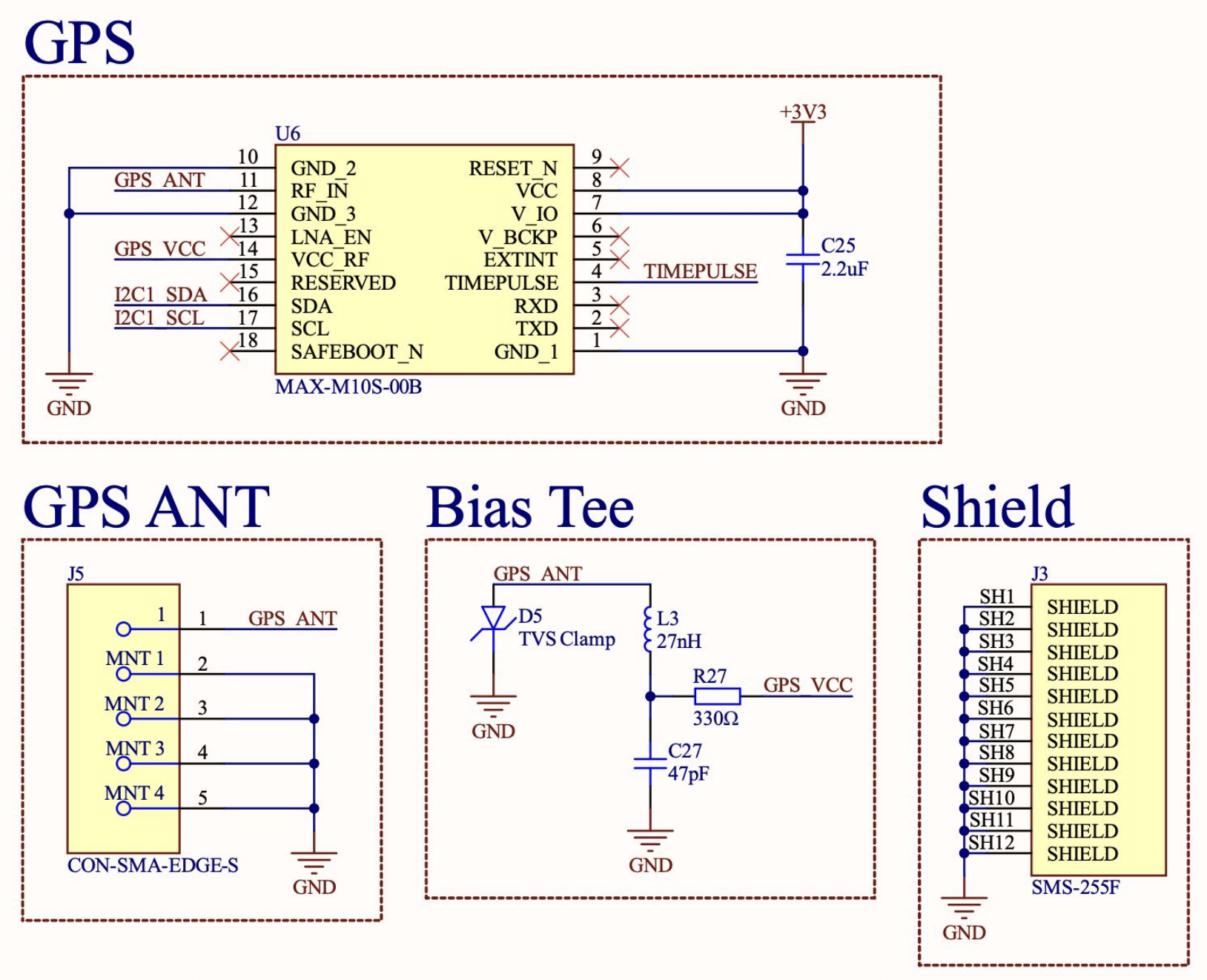
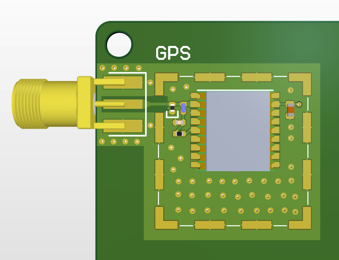
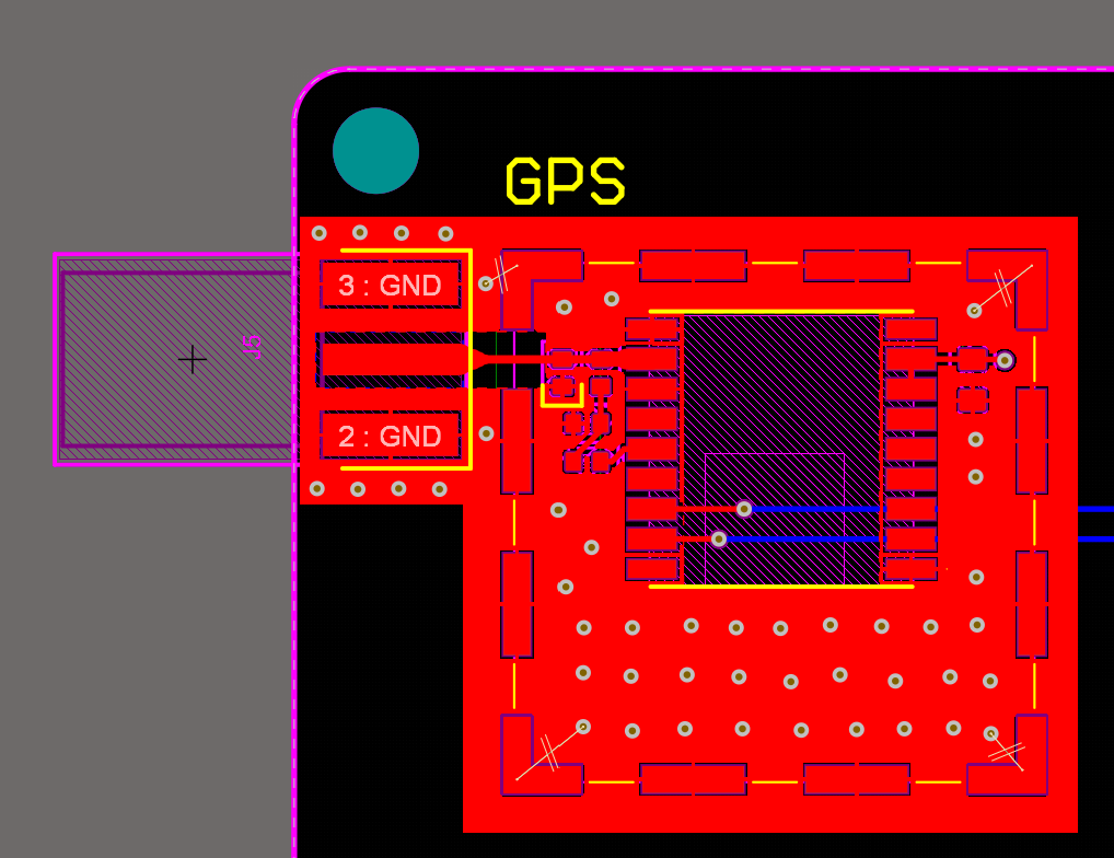
The board contains a u-blox Max-M10S GNSS module integrated directly into the PCB with a side-mounted SMA connector. Features a short, impedance-matched trace and a bias tee to provide power for the active antenna. Because of the sensitivity of the signal, the module is housed within an RF shield as a precautionary measure to prevent signal integrity issues. Additionally, the GNSS circuitry was laid out as far as possible from the buck convertors to prevent additional unwanted noise.
900MHz Radio Transceiver
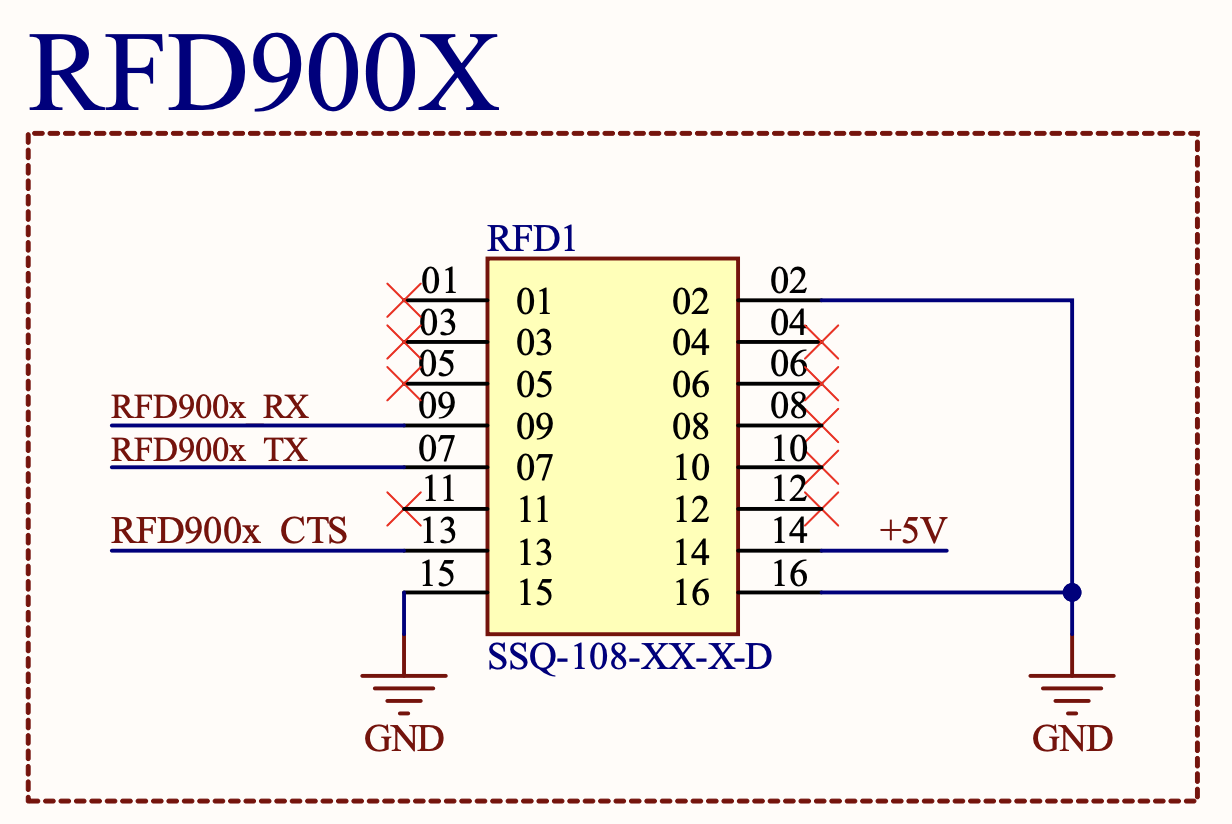
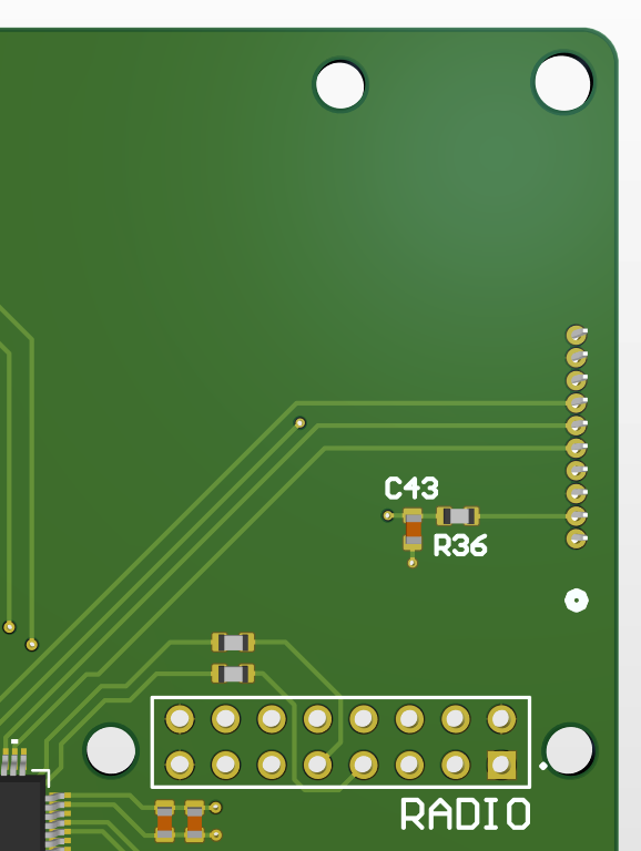
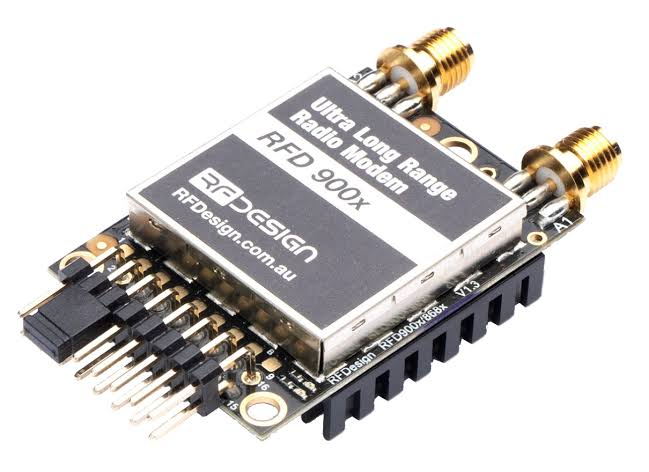
A 900MHz radio transceiver module mounts directly to the PCB and transmits UART packets sent from the MCU over radio to the base station.
Dual CAN Bus Network
The telemetry board has connections for two distinct CAN bus networks. A CAN FD network connects the critical boards on the car that are essential for the operation of the car and functionality of its throttle, horn, cruise control, turn indicators, driver display, and e-stop. A secondary standard CAN network exists for non-critical systems like telemetry data collection and support for additional sensor in the future like strain gauges.
Rear Light Controls
The telemetry board also controls the rear lights of the car including brake lights, turn signals, and the strobe fault indicator light. A high-side switch is used to switch these +12V loads.
E-Stop Input
The large emergency stop button on the top of the car is read by the telemetry board and when pressed alerts the battery management system to open the main battery contactors. The button latches and prevents the car from driving until it is power cycled and the fault is cleared. The button operates on a 12V logic level to provide resilience against EMI generated in the car by the radios and motor. The input is converted to a +3V3 logic level on the PCB so it can be read by the MCU.
Power and Protection Circuitry
The board is powered off the 12V bus of the car and features two buck convertor circuits to generate a 5V and 3.3V supply. Buck convertors were chosen for their high efficiency. The 12V input passes through a p-channel MOSFET for reverse polarity protection and e-fuse for over-current and short-circuit protection.