Bus Tracker
Overview
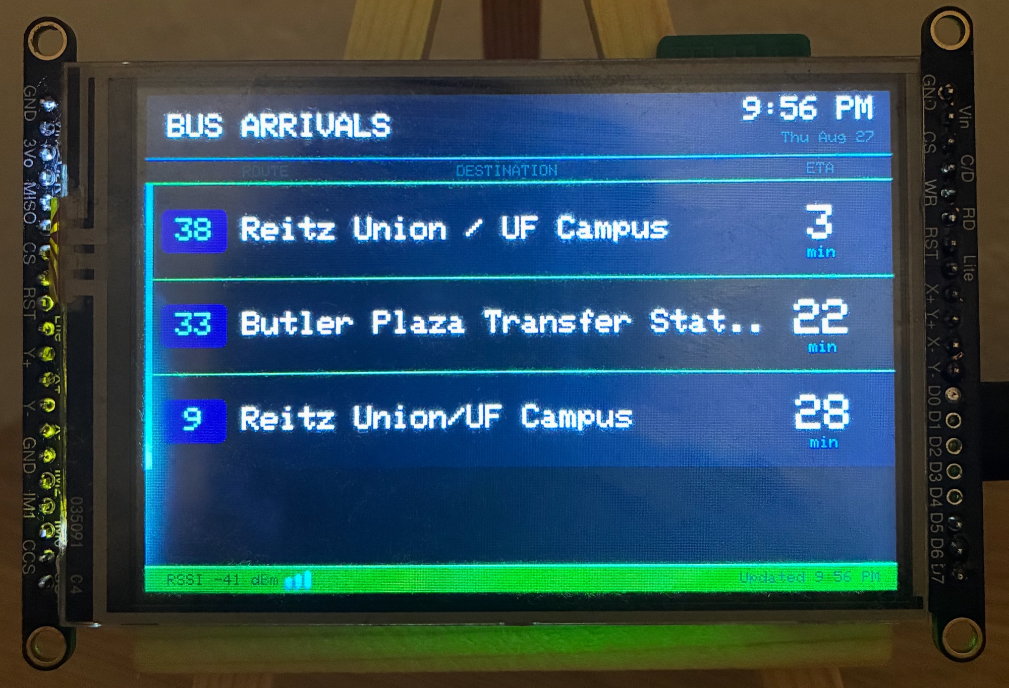
I created this project because I was tired of checking the bus times on my phone every morning for my stop. This device is intended to be connected to your home Wifi network and sit in the kitchen, displaying the live arrival times for your bus stop.
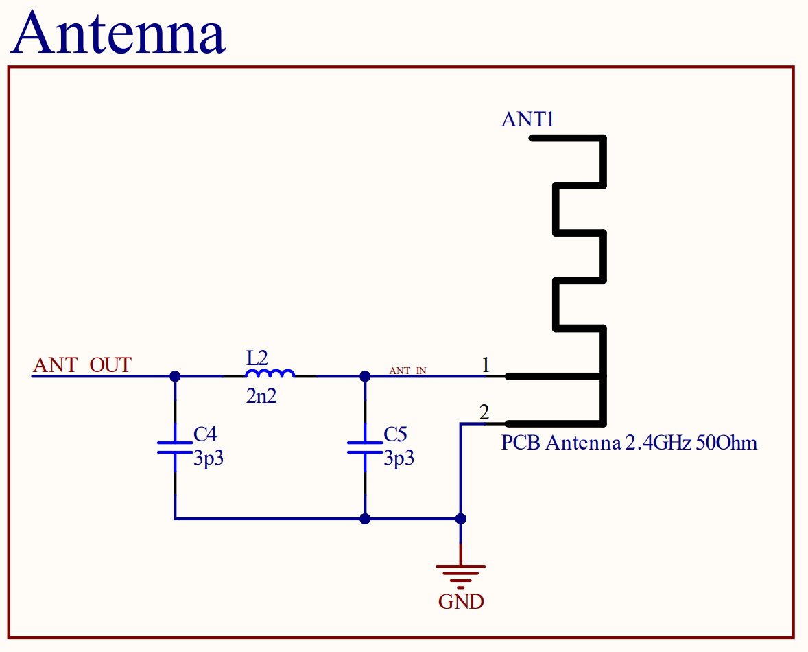
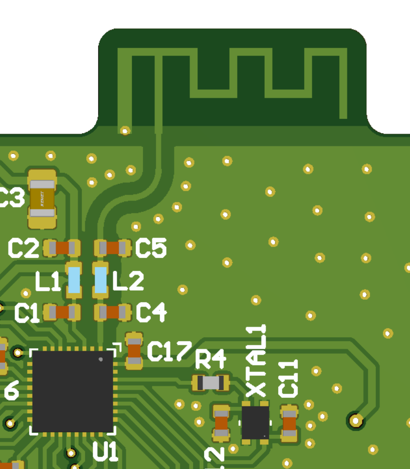
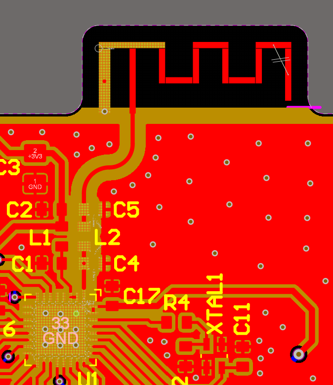
Wifi Trace Antenna
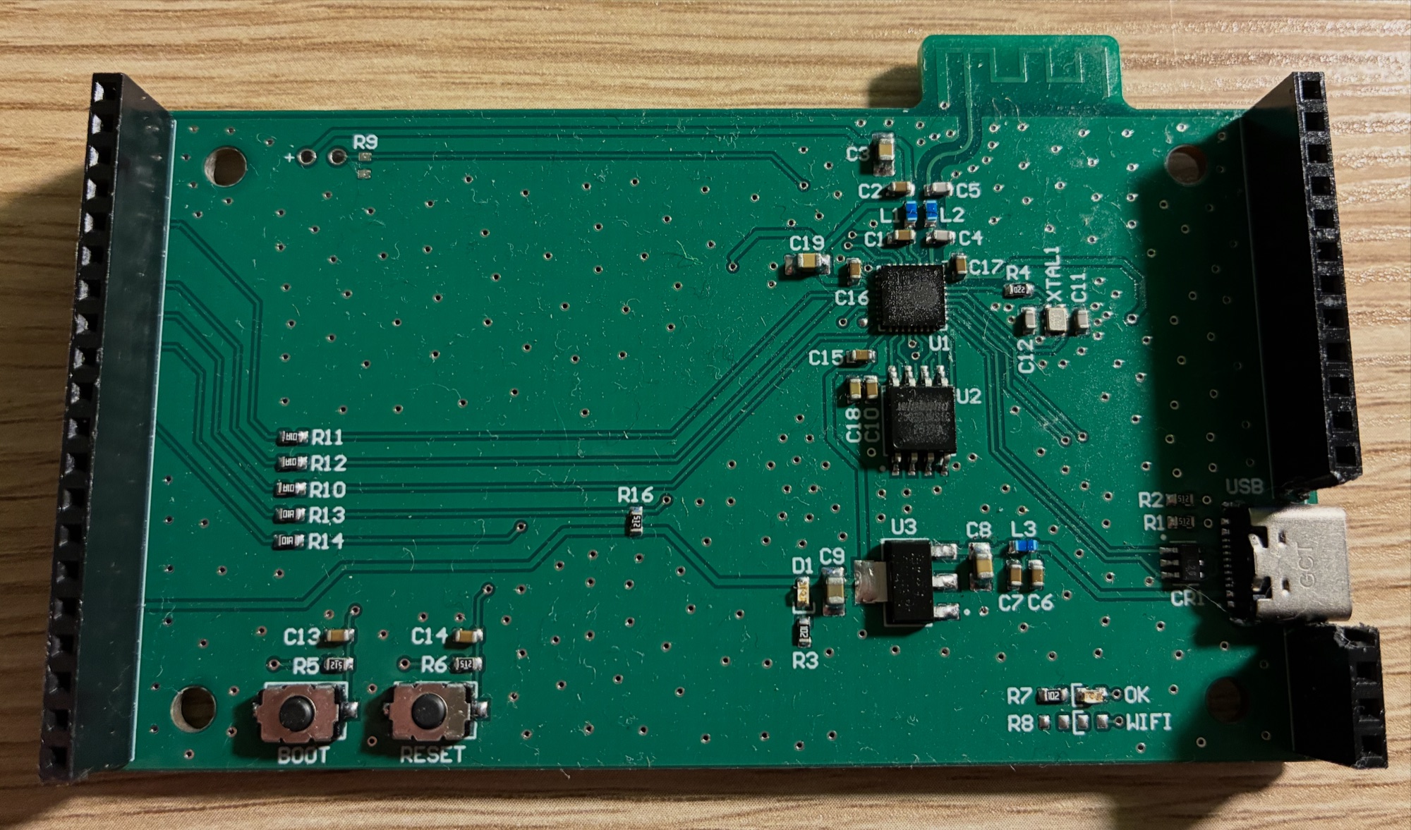
Features a 2.4Ghz trace antenna for Wifi connection. Followed high-frequency layout principles including trace width calculation and a PI impedance matching network for best the Wifi range performance.
Auto-Dimming Backlight
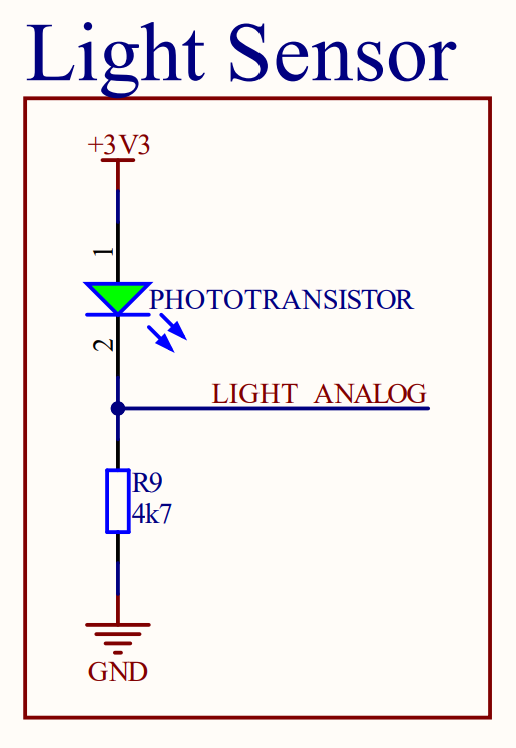
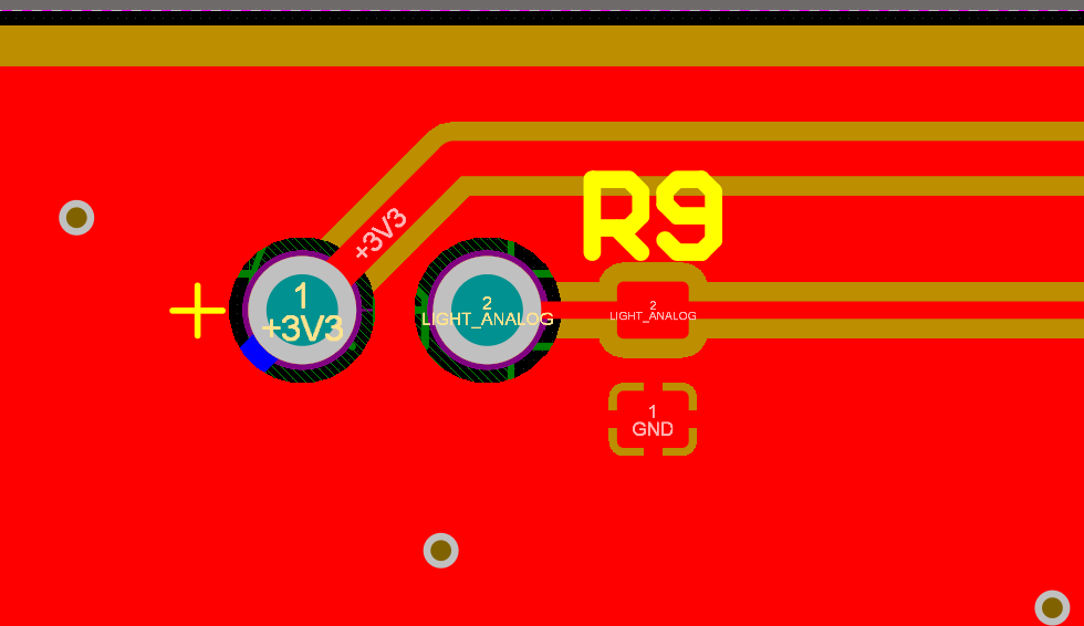
A phototransistor senses the ambient light in the room to dynamically adjust the backlight brightness of the display. A resistor biases the phototransistor to create a voltage divider, which output is measured by an internal ADC on the microcontroller. The display backlight is driven by a PWM signal. The duty cycle is adjusted based on the ambient light in the room.

Microcontroller
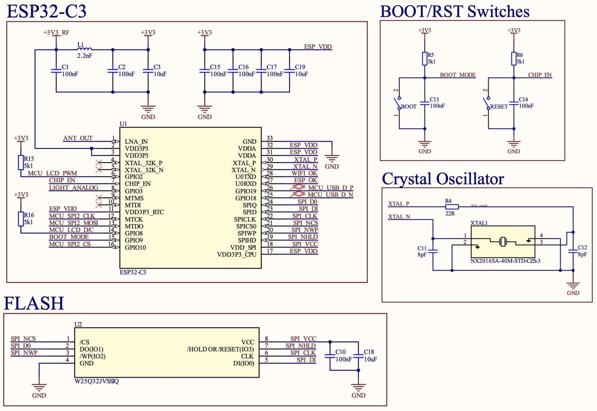
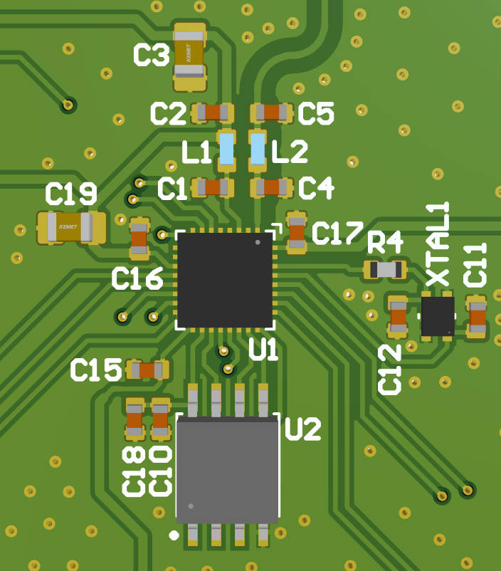
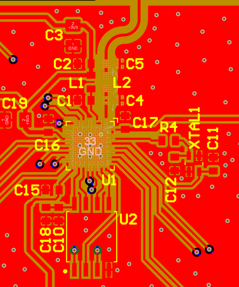
Uses an ESP32-C3 microcontroller for its modern architecture, low power consumption, wireless connectivity, integrated USB to JTAG programmer, and low cost. Paired with a 4Mb external SPI flash for program storage.
Power and USB
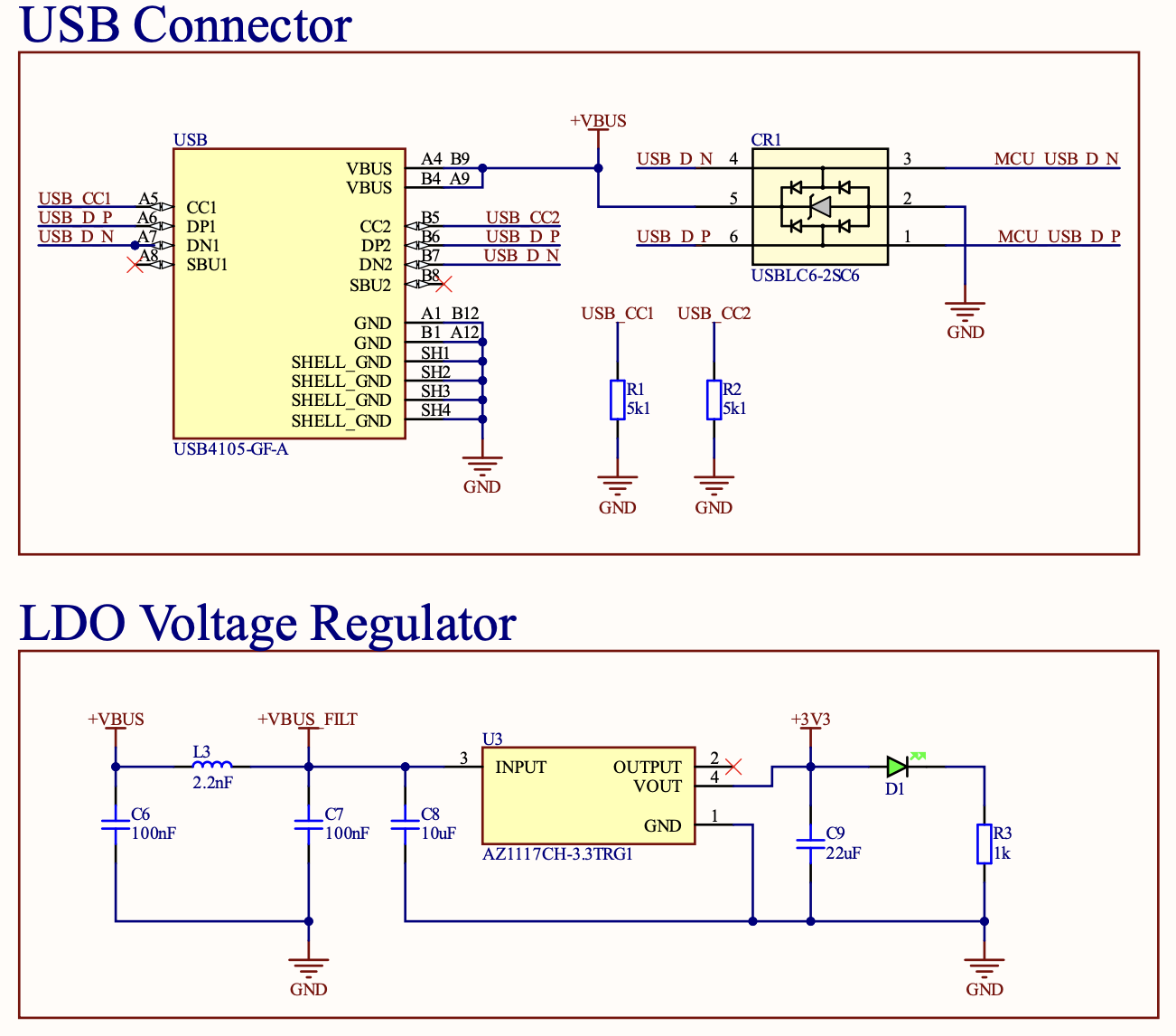
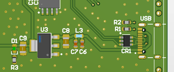
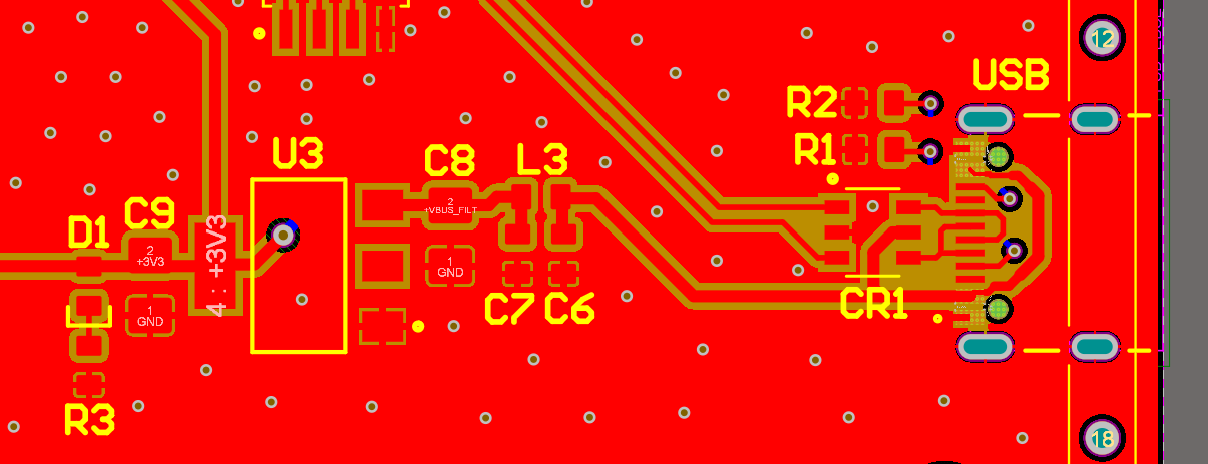
An LDO converts the 5V USB input to 3.3V for the microcontroller. A linear regulator was chosen for its simplicity and because of the small drop required between the input and output voltages.
Color LCD Display
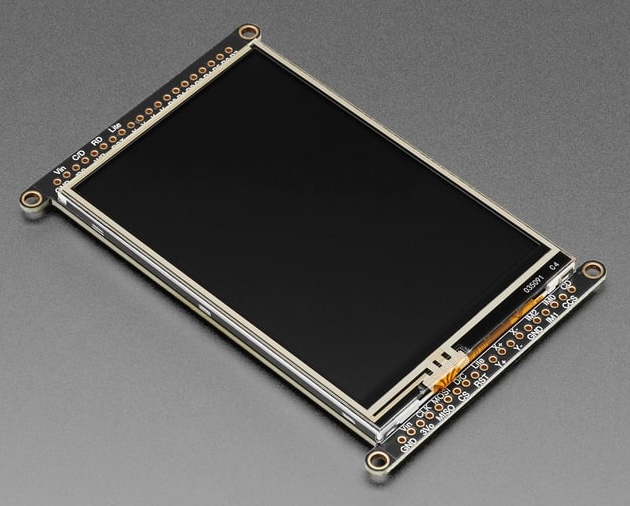
A color LCD display is connected over SPI.